As more and more stringent environmental policies adopted by various agencies a need for an Environment friendly blasting is a must. In order to have a good manual blasting operation a neat and clean blast room is required. CLEANBLAST with its years of experience in design and installation of various Blast Rooms in India and Middle East is a trusted partner for your return on investment.
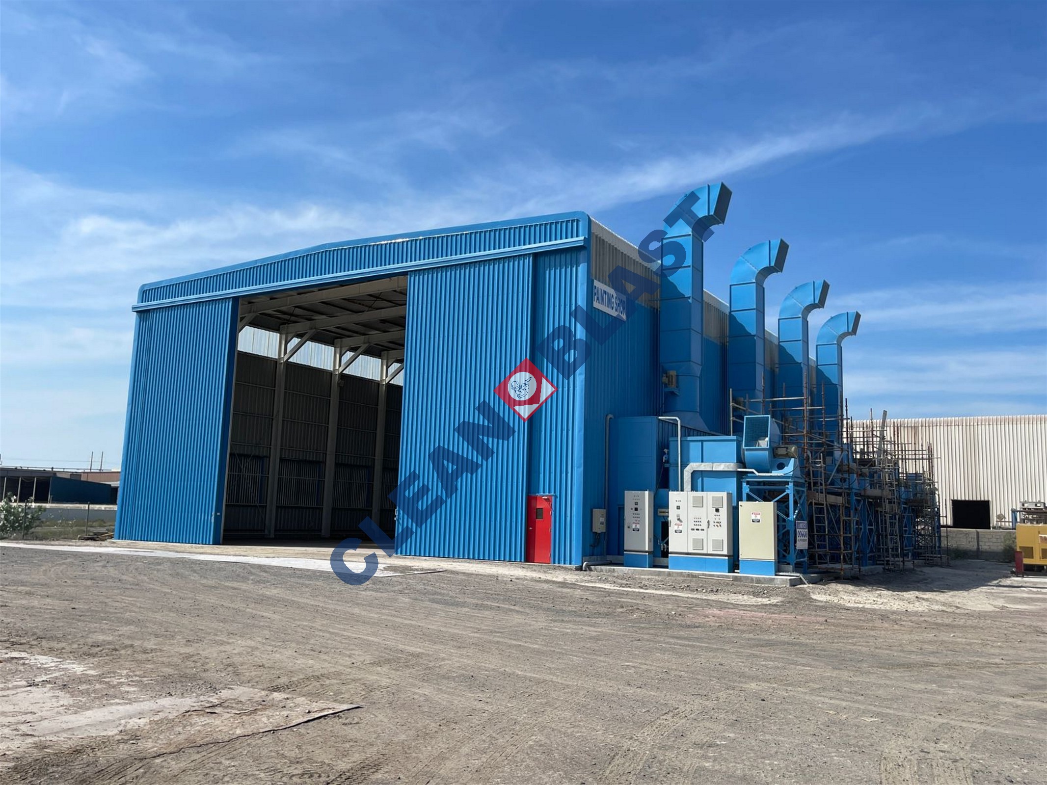
Typical enclosure of a blast room will be made out of m. s. folded and bolted panels or PU form sandwich panels duly supported with formed structural members. Booth will have option of semi-automatic or full automatic recovery system fitted. The internal walls of a blasting booth are protected by abrasion resistant rubber sheets. Proper illumination using blast proof LED lighting are necessary for a higher produc- tivity. ‘Man Door will be provided on the sidewall of the booth. Air inlet louvers and exhaust hoods are provided on the front and rear wall of the booth respectively for ventilation and dust extraction. The jobs can be handled in and out of the blast room manually, by fork lift or in trolleys. Generally, Steel Grit and Garnet are widely used as preferable abrasive in a blast booth.
After placing the job in the blast room the operator should enter the blasting Booth, through the ‘Man Door’, fully protected with operator’s gear. The dust collector, grit recovery system and the lights put ‘ON’. The operator should connect the air supply to air regulating valve fitted at operator’s waist belt. Open this valve for breathing air supply to the helmet.The operator should operate the remote control provided on blast hose directing the blast nozzle on the job. The abrasive gushing out of blast nozzle would clean the job. The operator should observe and clean the complete job. Put another job for blasting and repeat the process.During blasting operation, the abrasive falls on the floor and should be collected sieved, air washed and segregated and then feed to the blast hopper/storage cum feed hopper for re-circulation.
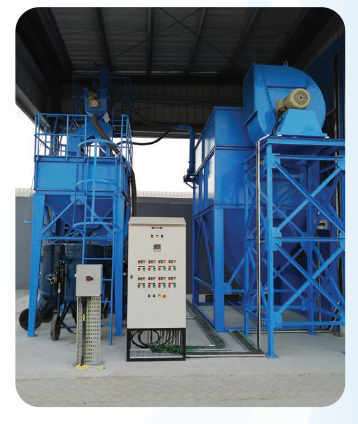
Recycling system is provided to reclaim the useful abrasive from the spent abrasive . The spent abrasive is mixture of broken abrasive , dust , useful abrasive and other contaminants . The proportion of useful abrasive reclaimed depends on the initial size and type of abrasive used . In case of steel abrasive the brake - down rate is nominal, whereas expandable abrasive has very high rate of brake-down.
Dust collector plays a significant role in the efficiency of a blast cleaning plant . Good operating conditions for the operator in a blast chamber is essential and equally so is the dust removal and separation of abrasive in a blast plant. Lot of dust is generated during blast cleaning process due to removal of the scaling, rust etc of the metal being cleaned and disintegration of the blasting media. This leads to air pollution as well as low visibility for the blaster. The air born dust also tends to settle on the cleaned surfaces defeating the process. A dust extractor is employed to extract the air born dust from the blast room. But only extraction of the dust from the room will still pollute the surrounding atmosphere hence it is necessary to arrest the extracted dust for safe disposal. The dust collector takes care of all the aspects addressed above. Filter housing placed outside the blast room is connected through properly designed ducts, for trapping the extracted dust and exhaling reasonably clean air to the atmosphere. A centrifugal fan is employed to create slight negative pressure in the blast room and suction through the filter housing and ductwork. The blast room
has provision for inlet air so that a cross or down draft is created in the blast room taking away the air born dust to the filter housing . Cartridge filter type Dust Collector is provided to extract dust from the shot blasting and air wash separator system. It is fabricated out of 2/3 mm plates suitably reinforced . Cartridges of non-woven cellulose /polyester are provided to filter the dust laden air. Cartridges divide the dust collector into two zones:-
1. Dust laden or incoming zone, and
2. Clean air or exhaust zone.
Dust laden air is sucked from the blast system and conveyed to the dust collector system through various ducting at conveying speeds of 2000 to 3800 ft/min. As the dust laden air enters in the dust collector , it expands due to increase in the cross section and is directed upward towards the filter. The combined effect of expansion and change in direction helps separation of larger particles of dust, which fall and get collected in the hopper provided below the dust collector. As the air passes through the filter, particles up to 10 microns size get filtered . The filtering , mainly due to the formation of thin layer of "Filtering Cake ", which forms within few seconds and is primarily responsible for efficient filtration . The clean air passing through the filter is sucked by the exhaust blower and exhaled to the atmosphere . As the filtration takes place , the thickness of filtering cake keeps increasing . This increase in the thickness of the filtering cake offers higher and higher resistance to the air fl ow and reduces the effectiveness of the extraction system . It is , therefore , necessary to remove this cake , which is achieved by reverse pulse jet. Strong jet air at a pressure of 6 kg/cm2 is shot for a fraction of a second in the opposite direction of airflow through the This increase in the thickness of the filtering cake offers higher and higher resistance to the filters. This action is sequentially carried out through all these filters. This knocks off the layer of dust deposited on the filter area . The loose dust falls off and is
collected in the hopper. The cyclic action continues to clean the filters, a couple of them at a time. A simple water manometer is provided to indicate pressure difference across the filter cartridge.
Totally enclosed sheet steel fabricated motor control center is provid- ed with desk type design for front operation and access to interior from front hinged door. The panel is coated with anti-corrosive paint after pre-treatment and stowing enamel. The panel is complete with all internal wiring and connections and generally comprises:-
1. TPN fuse switch unit
2. Supply "ON" indicating lamps
3. Voltmeter with selector switch and back-up fuses
4. Ammeters for all motors above 15 HP
5. A set of 3 ½ bus bars
6. DOL starters for all motors with necessary back-up fuses.
7. Star delta starters for all motors from 10 HP onwards
8. Sequential locking system for abrasive conveying drives
9. Defeat sequence system for maintenance purpose
10. Various interlocking and safety system
11. Emergency stop push button.
Advantages of Blast Room
• Clean environment around the facility
• Low production cost of blasting was the abrasive are recycled inside the room
• Meeting all the local EHS requirements
• Proper visibility so that the blaster can get high productivity
• Good ventilation inside the room
• Most versatile for all intricate shape and sizes of components
CLEANBLAST has got the expertise to customize the blast room as per
the customer requirements
A Blast room consist of following accessories
1. Enclosure Room or Booth
Can be either of sheet metal , sandwich panel or masonry construction
2. Inlet Air Louvers
3. Dust Extraction System
4. Abrasive recycling System
5. Shot Blast Quality Rubber Lining
6. Blast Proof Light
7. Control Panel
Following factors determines the specification of a standard blast room.
• Size of the job to be blasted
• Production Rate and No of blasters in the room
• Type of abrasive used and
• Type of recycling system to be adopted
• Work piece material handling requirement
The spent abrasive is reclaimed through following devices:-
a) Feed Hoppers
Steel sheet collection hoppers are provided at floor level above cross screw conveyor . The cross screw conveyor is running below the collection hoppers . Manually swept and collected abrasive is directed in the feed hopper . The abrasive from the feed hopper is transferred by gravity to screw conveyor running below the blast room floor. In case of full recovery system the cross conveyor receives the spent abrasive from the longitudinal screw conveyors
b) Conveyor
This conveyor is provided below the collection hopper . The abrasive from the blast room fl oor is manually swiped & transferred to the collection hopper . The collection hopper is delivering the abrasive to the conveyor below it for
transferring it to bucket elevator bottom boot for further transfer.
c) Bucket Elevator
Centrifugal discharge type bucket elevator scoops the abrasive from the bottom boot and discharges the same to a three deck vibrating screen separator. The steel sheet enclosure houses the boot and head drum pulleys . The drum pulley shafts are mounted on adequately sized sealed bearings ensuring free rotation . A take -up arrangement is provided on the head pulley to facilitate proper tensioning of elevator belt. A shaft mounted geared motor is employed to drive the bucket elevator. One suction hose is also provided on the bucket elevator to take away air borne dust in the bucket elevator enclosure to the dust collector.
d) Air wash separator
The fundamental design concept of the Separator operates in a wide variety of blast cleaning applications. The separator can be furnished in various sizes and capacities. Small units have gravity fed distribution and “overflow” feature. Medium and large capacity units for de-scaling applications may be equipped with distributing screws only. For foundry type applications with course scrap in the abrasive mixture the separator may be furnished with both scalping drum and distribution screw. The drum provides an additional screening for removal of scrap while its external screw gives total abrasive distribution along the separator lip. All separators have the exclusive “overflow” and re-circulation of abrasive mixture. The abrasive mixture curtain falling from the separator lip passes through the air wash zone. High velocity air passing through the curtain carries dust and sand particles into a collection hopper for discharge. The primary skimming plate is adjusted to divert to the collection hopper only that portion of sand or fines not containing good abrasive. The secondary skimmer plate may be adjusted to divert a small portion of the abrasive containing any leftover sand particles. The abrasive-sand mixture collected
by the second skimmer plate is then re-circulated through the abrasive handling system. The separator is having two skimming plates. The abrasive delivered by bucket elevator to the rotary screen gets collected behind a metering plate along the length. This allows the collection of abrasive along the full width of the plate and then fall in the form of a uniform curtain. Further the abrasive travels as explained above. In this process the air wash is taking at two places and abrasive grading and cleaning is achieved very effectively. The fines, refuse and dust are separate and the useable broken abrasive is also re circulated, saving costly abrasive. A suction hose connected between air wash and dust collector carries the dust separated in the air wash section to the filter housing.
e) Sequential Control
The complete system is sequential for proper operation and safety purpose. The electrical control circuit is interlocked for the sequential operation of the recycling system.
f) Storage Bin
One steel plate abrasive storage bin with adequate capacity receives clean abrasive from the vibrating screen.
g) Abrasive Gate
Each pressure blast vessel is fed abrasive from storage bin through an abrasive control gate located close to the vessel.
In order to ensure fairly uniform cross draft across the blast room particularly at the level of operation, extraction hood is essential. By providing small resistance across the perforated plate, the extraction is spread over larger area thus ensuring fairly uniform cross draft. The extraction hood is also expected to trap useful abrasive escaping to the dust collector. The extraction hoods are strategically located inside the blast room opposite fresh air supply louvers so that most of the air extracting the dust will blow across the operating area.
The function of the Fresh Air Supply Louvers is to allow outside air to enter the room for extracting the dust and getting exhausted after filtration. The fresh air supply louvers are expected to trap any abrasive trying to escape during blasting and admit only outside air. The Exhaust hood and fresh air supply louvers are the most important features of the blast room ventilation system, which are ignored by many manufacturers.
Rolled M.S. sheet 10/12 swg ducting with dampers elbows & expansion joints connect the various dust extraction points with filter bag chamber. The dust collector unit is generally placed just near or behind the shot blasting plant. The length of intermediate ducting will depend on the general layout and location of the Dust Collector and hence the same is not considered in our present scope of supply.
For prevention of scoring of room enclosure walls, rubber sheets of low shore hardness are fixed in a loosely hung manner. Abrasive particle hitting the rubber sheets looses its energy rapidly and falls down with minimum breakage and less scoring in the rubber sheet. The rubber sheet fixing hardware includes specially formed 'Z' sections, and 'C' shaped flat. The 'Z' member is fixed to the wall through anchor bolts. Elongated punched holes in 'Z' section and 'C' channel make the fixing of the rubber sheet with nuts and bolts very convenient. The 'C' Channel provides uniform pressure along the width of the rubber sheet and reduces chances of tear at the punched holes.
@2022 Clean Blast International L.L.C. All rights reserved.